
Progress method

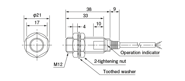
Electrically detects the movement of the indicator pin of progressive valve.
Proximity sensor monitors the movment of the indicator pin and detects a system or valve failure.


| E2E-X2E1 | E2F-X2E1 | E2F-X2Y1 | |
|---|---|---|---|
| Power Supply Voltage | DC12〜24V | AC24〜240V | |
| Use Voltage range | DC10〜40V | DC10〜30V | AC20〜264V |
| Output Form | DC 3-wire NPN | AC 2-wire system | |
| Detection Distance | 2mm±10% | ||
| Setting Distance | 0〜1.6mm | ||
| Standard Detection Object | Iron 12×1mm | ||
| Protection Grade | IEC standard IP67 | IEC standard IP68 | |
| Model | Part Number |
|---|---|
| E2E-X2E1 | 733225 |
| E2F-X2E1 | 730797 |
| E2F-X2Y1 | 730721 |
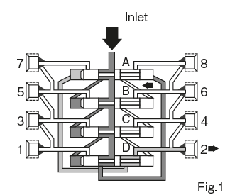
Grease that has been pumped by the pump or grease gun comes in through the inlet at the top of the block. The delivered grease passes through the darkened port to the right of the piston "A" and moves the piston "A" to the left directions. At this time, the grease on the left side of the piston "A" is discharged from the outlet No. 2 through the port shown in light color.
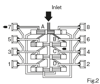
When the piston "A" strokes to the left direction fully, the port leading to the right side of the piston "B" is connected as shown in dark color in Fig. 2, and the grease from the Pump passes through this port and the piston "B" Move to the left directions. At this time, the grease on the left side of the piston "B" is discharged from the No. 7 outlet through the port shown in light color.
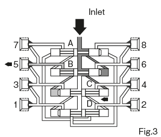
As before, when the piston "B" is fully stroked to the left direction, the port leading to the right end face of the piston "C" is connected as shown in dark color in Fig. 3, and the grease passes through this port , Move the piston "C" to the left directions. At this time, the grease on the left side of the piston "C" is discharged from the 5th outlet through the port shown in light color.
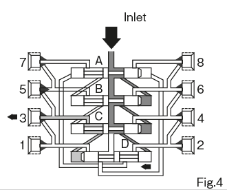
When the piston "C" is fully stroked, as shown by the dark color in the right figure, the port leading to the right end face of the piston "D" is connected, and the piston "D" is moved in the left directions. At this time, the grease on the left side of the piston "D" is discharged from the 3rd outlet through the port shown in light color.
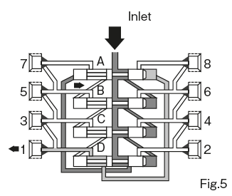
This time, as a result of full stroke of the piston "D", the port leading to the left end face of the piston "A" is connected as shown in dark color in the figure, and the piston "A" is moved to the right directions. At this time, the grease on the right side of the piston "A", which previously worked as hydraulic fluid, is discharged from the first outlet through the light colored port. From then on, grease will be discharged in the order of 8, 6, 4, 2, 7, 5, 3, 1 outlets in the same manner.
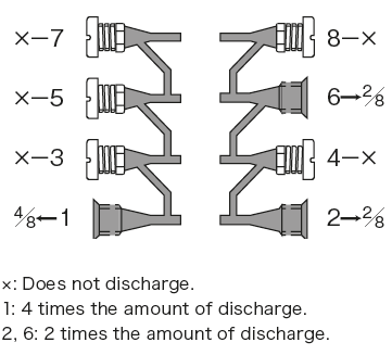
● Setting of discharge amount
Each Discharge Port discharges 0.2 ml / stroke of grease when the pump is activated. When one Discharge Port is closed, the amount of the closed part is added to the next Discharge Port and discharged. Example) Closing # 8 will discharge 0.2 ml × 2 = 0.4 ml into # 6. When # 7, 5 and 3 are closed, 0.2 ml × 4 = 0.8 ml is dispensed to # 1. In this way, you can set the required amount for the lubrication point. However, do not close # 1 and 2 as they are switching valves. The whole will not work.
● Notes
1. Only dedicated fittings should be used for Discharge Port of AP and SP type valves.
2. When installing the Discharge Port Nipple with a check of the dedicated joint on Grease Discharge Port, make sure that the bypass hole blocking ring is set. Also, when attaching a plug to Grease Discharge Port, be sure to remove the bypass hole blocking ring. If you install the plug with the bypass hole blocking ring set, the entire valve will not operate.
3. Tighten the Checked Discharge Port nipple or compression nut slightly to ensure the bypass hole blocking ring is set.
4. When screwing a dedicated joint into Grease Discharge Port, assemble it in order from the top or bottom. If you start assembling from the middle Discharge Port or skip along the way, the spanner does not turn sufficiently and can not be assembled.
5. When screwing the plug into Grease Discharge Port, tighten slightly. Also, be sure to use a new Target Washer with a new copper washer that has been used once.